

|
|
Main Memory With The Contents Are In Disagreement Ch341a Top — Chip |
Post Reply 
|
| Author | |
Tom H 
Admin Group 

Joined: 05 Jan 2012 Location: San Diego, CA Status: Offline Points: 6024 |
 Post Options Post Options
") Thanks(1) Thanks(1)
 Quote Reply Quote Reply
 Topic: IPC-7351 & IPC-7352 Standard SMD Terminal Leads Topic: IPC-7351 & IPC-7352 Standard SMD Terminal LeadsPosted: 07 Apr 2024 at 1:13pm |
|
Here are the 15 Standard Surface Mount Terminal Lead Forms represented in the IPC-7351 and IPC-7352.
The first bend in the lead is referred to as the Knee. The second bend is the Heel and the end of the lead is the Toe. For Grid Array and BTC leads, the solder joint goal is a Periphery. 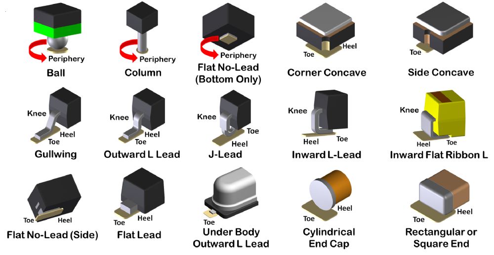 |
|
 |
|

|
|
|
|
|
Tom H
Admin Group
Joined: 05 Jan 2012 Location: San Diego, CA Status: Offline Points: 6024 |
Post Options
Thanks(0)
Quote Reply
Posted: 07 Apr 2024 at 1:19pm |
|
The anatomy of the human leg is used to determine the Surface Mount Toe and Heel of the solder joint definition.
 |
|
|
|
|
circuits
New User 
Joined: 13 Aug 2024 Status: Offline Points: 2 |
Post Options
Thanks(0)
Quote Reply
Posted: 13 Aug 2024 at 6:39am |
Main Memory With The Contents Are In Disagreement Ch341a Top — ChipUse 90% isopropyl alcohol and a toothbrush to clean the chip legs. The gold standard for command-line stability. 4. The "Blank Check" Workflow : Switch to ASProgrammer or NeoProgrammer, which often have better chip detection and "Unprotect" features. 3. Verify Voltage Compatibility : If the software detects the chip as a generic variant or a different capacity (e.g., detecting a W25Q64 as a W25Q32), the sector map will be incorrect, failing the verification phase. Use 90% isopropyl alcohol and a toothbrush to : Clean the chip pins thoroughly with 99% Isopropyl Alcohol (IPA) and a toothbrush. Re-seat the clip, ensuring it sits perfectly parallel to the chip. Ensure the ribbon cable leading from the clip to the SOP8-to-DIP8 adapter board is securely pushed in. Motherboard Power Parasitism (In-Circuit Programming) "Top" chips (often found on router PCBs, LG monitor mainboards, or older laptop BIOS) are notoriously sensitive. They have: Newer laptops and motherboards utilize low-voltage 1.8V SPI chips (e.g., Winbond W25Q64FW or Macronix MX25U series). Blasting a 1.8V chip with a 3.3V or 5V current without a dedicated 1.8V Level Adapter will cause instant verification disagreement errors or permanently fry the silicon. Step 3: Ditch Outdated Software for Modern Alternatives The "Blank Check" Workflow : Switch to ASProgrammer To understand the concept of "disagreement" in this context, one must first define the relationship between the physical chip and the logical "main memory." The physical chip—usually a SPI Flash memory IC—acts as a permanent storage vessel for the system’s firmware or BIOS. "Main memory," in this context, can be interpreted as the expected operational state of the computer or the logical data structure that the engineer believes should be present. A "disagreement" occurs when the contents read from the chip do not align with the expected values, or when the chip itself resists the programmer’s attempts to read or write due to status register locks or voltage mismatches. It is a conflict between the hardware’s reality and the operator’s intent. If Step 1 fails, you must fix the voltage. In the world of hardware debugging and firmware recovery, few messages are as quietly alarming as the realization that a chip’s main memory contents are in disagreement. For engineers and hobbyists using the ubiquitous CH341A series programmer—often referred to as the "CH341A Top" due to its common black PCB design—this discrepancy signals a fundamental breakdown between what should be stored and what is being read. This essay explores the nature of memory disagreement, the role of the CH341A in detecting it, the likely causes, and the implications for system integrity. : Clean the chip pins thoroughly with 99% This comprehensive guide explores every possible cause of this error and provides a step-by-step troubleshooting plan to get your CH341A working again. Let’s go through the most common causes of the disagreement error before we jump into troubleshooting. Ensure the red wire on the ribbon cable aligns with Pin 1 (the dot) on the chip. While it requires soldering skills and equipment, this step has the highest success rate for overcoming connection, power, and interference problems. The time saved in frustration is well worth the effort of desoldering. When a programmer writes data to a flash chip, it performs a follow-up pass to read the chip and compare it byte-for-byte with the source file. If even a single bit mismatches, the software throws a disagreement error. The root causes generally fall into four categories: By ensuring a stable electrical connection and using modern software, you can usually bypass this error and get your device back up and running. |
|
|
|
|
Post Reply
|
|
| Tweet |
| Forum Jump | Forum Permissions You cannot post new topics in this forum You cannot reply to topics in this forum You cannot delete your posts in this forum You cannot edit your posts in this forum You cannot create polls in this forum You cannot vote in polls in this forum |


 Topic Options