Tiger Touch II
ORDER CODE: AVOTIGERTOUCH2Now boasting a 100% brighter screen, increased processing power, and faster graphics engine, the Tiger Touch II is the most specified Titan console.
The Avolites Tiger Touch II represents the perfect combination of power and portability. This third-generation console is packed with enough power for complex shows, yet small and light enough to fly in standard hold luggage. The console features SMPTE timecode support and a redesigned button layout to match the entire Titan range.
In order to update the console to version 12 of the Titan, it will be necessary to purchase and install a USB dongle called AVOKEY.
Serial 02006 - 03065
You need to order:
- AVOKEYINT
- 1x5 way to USB-A Cable (spare part code 8000-6102)
Once you've received your AVOKEYINT and 1x5 way to USB-A Cable, you will be required to connect the USB-A Cable to the motherboard. This cable will provide an additional USB port for the AvoKey.
Click here to view the installation guide: https://www.avolites.com/Portals/0/Downloads/Manuals/AvoKey/8000-6102 TT2-2-3K AVOKEY upgrade with 1808-0028.pdf
Serial 03066 - 4020
You need to order only AVOKEYINT
Once you've received your AVOKEYINT, you will be required to connect this directly to the available (Blue) USB port inside the console (on the motherboard).
Click here to view the installation guide: https://www.avolites.com/Portals/0/Downloads/Manuals/AvoKey/8000-6101 TT2 AVOKEY no cable.pdf
Serial 04021 - 05001
You need to order only AVOKEYINT
Once you've received your AVOKEYINT, you will be required to connect this directly to the available (Red) USB port inside the console (on the motherboard).
Serial 5001 and above include a factory fitted AvoKey.
Therefore, you do not need to purchase an AvoKey.
Main features:
- 10 pageable playbacks, 60 pages.
- 10 static playbacks - perfect for instant access.
- 100% brighter 15.6" screen.
- Three metal shaft optical encoders offering luxurious precision.
- MIDI support for MIDI Notes and MIDI Timecode.
- Built in UPS.
- 4 physical DMX outputs, up to 16 over ArtNet or sACN - 8192 channels.
- Supports Titan Network Processors for DMX expansion up to 64 universes.
- Trigger inputs.
- Dual Ethernet port.
- Expand your control surface through wings, DMX In or MIDI.
- Dedicated cue stack control.
- Support for external touch screen.
- 10 programmable executor buttons.
- Conveniently accessible front loading USB.
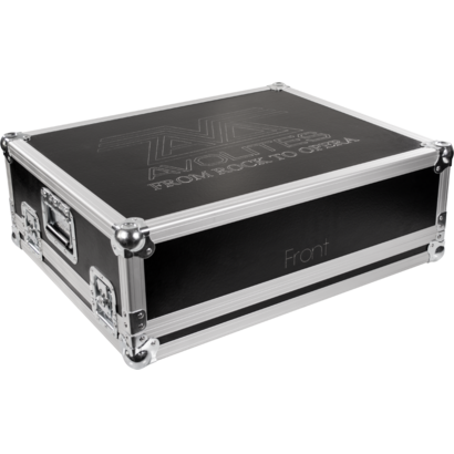
- Dimensions (WxHxP): 675x435x147 mm (console only); 750x620x300 mm (console in flight case).
- Weight: 15.2 kg (console only); 29.40 kg (console in flight case); 31.70 kg (console packed in flight case).