 ЮЂаХЕчФдАцПЭЛЇЖЫ
 ЖЄЖЄpcПЭЛЇЖЫ
 ПфПЫЭјХЬPCЖЫ
 АЂРядЦХЬPCПЭЛЇЖЫ
 360МЋЫйфЏРРЦїX
 ЯђШеПћдЖГЬПижЦШэМў
 ToDeskдЖГЬПижЦШэМў
 Л№КќфЏРРЦїPCАц
 фЏРРЦїvipВхМўЦЦНтАц
 CareUEyes(РЖЙтЙ§ТЫЛЄблШэМў)зюаТАц


Input the magnitude in the Properties panel (e.g., a uniform planar dead load of in the global Z direction).
Choose your type: Slab (horizontal/inclined) or Wall (vertical).
Use the "Report Generator" to create customized documentation.
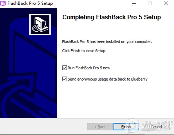
Open Advance Design and select New Project .
Once the calculation completes, Advance Design transitions to the phase. Visualizing Internal Forces
For more information on Graitec Advance Design, including tutorials, webinars, and documentation, visit the Graitec website. You can also access a range of tutorials and videos on YouTube and other online platforms.
Use the Climatic Load Generator (Wind/Snow) for automatic wind pressure generation based on building geometry 1.2.1.
Model Mode: Manages structural geometry, material properties, systems (layers), and load cases.
Click on the base nodes or lines of your structural elements to apply the boundary conditions. 4. Step 3: Defining Load Cases and Combinations
An analytical model requires rigid boundary conditions to solve correctly. Go to the Model Ribbon > Supports .
Use the Library to select standardized steel sections (I-beams, hollow sections) or define concrete cross-sections. Draw Elements:
Navigating the user interface efficiently is key to a fast workflow. Advance Design uses a logical, ribbon-based layout structured around the lifecycle of a project. Understanding the Workspace
Right-click on in the Project Browser and select Create a Load Family . Create the necessary structural loads:
Advance Design features an advanced automated mesh engine. In the Analysis settings, specify your global mesh size (e.g., 0.5 meters for planar elements). Click Mesh to discretize the slabs and walls into shell elements.
Define the thickness (e.g., 200 mm) and material in the Properties window.
Full design, verification, and connector sizing (AISC & Eurocode 4) 1.2.2 .

 WIFIУмТыВщПДЦїЕчФдАц1.0 ТЬЩЋУтЗбАц
 VMcsCatЙЄОпЯфТЬЩЋУтЗбАц1.0.0.18 зюаТАц
 ВЪКчЙЄОпЯфШэМўзюаТБЫ2.0.2 ТЬЩЋАц
 ДхЭУАйЖШШШвщДЪХњСПВщбЏШэМў1.0УтЗбАц
 WiFi Mouse ProЕчФдЖЫжаЮФАц4.3.3зюаТАц
 ЭИУїЬЋПеШЫЬьЦјБэХЬ1.2зюаТАц
 ЙиМќДЪ4KЭМЯТдиЦї1.0зюаТАц
 ЕчФдАцШЋОжШШМќВщевШэМў1.0зюаТАц
 зщЖгСьШЁШ§ФъБЄЫўAPPВхМў1.0ТЬЩЋУтЗбАц
 Ььвў(CADСЊЭјЦСБЮШэМў)УтЗбЯТди1.0УтЗбАц
 гъПЮЬУПЮМўPDFЯТдиЙЄОпзюаТАц1.0.5УтЗбАц
 GIFТМЦСаЁЙЄОпзюаТАц1.0УтЗбАц
 ЖЄЖЄЗРГЗЛизюаТВхМўФЃПщЯТди0.1ТЬЩЋАц
 EduEditer(ПЮМўБрХХШэМў)ЯТдиАВзА1.9.9УтЗбАц
 HelperГіЬтЦїШэМўУтЗбЯТди1.02ТЬЩЋАц
 ЮТбдQQЙЄОпЯф(qqПеМфУыдоВщЪжЛњКХЖрЙІФм)2021УтЗбАц
 2345ЯЕСаШэМўЙуИцЕЏДАГЙЕзРЙНиЩОГ§ШэМў1.0.2ТЬЛЏАц
 ЖмЙЄвЛМќЛњЦїТыаоИФЙЄОпЦЦНтАц(ИНЪЙгУНЬГЬ)2021зюаТАц
 MyPublicWiFi(БЪМЧБОЙВЯэwifiШэМў)жаЮФАц27.0УтЗбАц
 здЖЏШыЛсСьОЉЖЙШэМўУтЗбАц1.0зюаТАц
 LightProxy(АЂРяАЭАЭзЅАќЙЄОп)1.1.40зюаТАц
 ДѓаЁЃК 102.9M


 ВЛЯоЫйЕФPCЯТдиШэМў
 PCЯТдиЙЄОпКЯМЏ
 pcЭјХЬПЭЛЇЖЫ
 ЬдБІЫЋЪЎЖўЙЄОпКЯМЏ
 ЕчФдфЏРРЦїКЯМЏ
ШШУХЦРТл
зюаТЦРТл